RGB Color Mixing
In this project, we vary the intensity of light with a potentiometer to build a colour mixer using a RGB LED.
Circuit
Components
- 1 Smowboard Think Mini
- 1 RGB LED
- 1 potentiometer
- 3 100 ohm resistors
- 3 male-to-male jumper wires
- 6 male-to-female jumper wires
- 1 screw driver
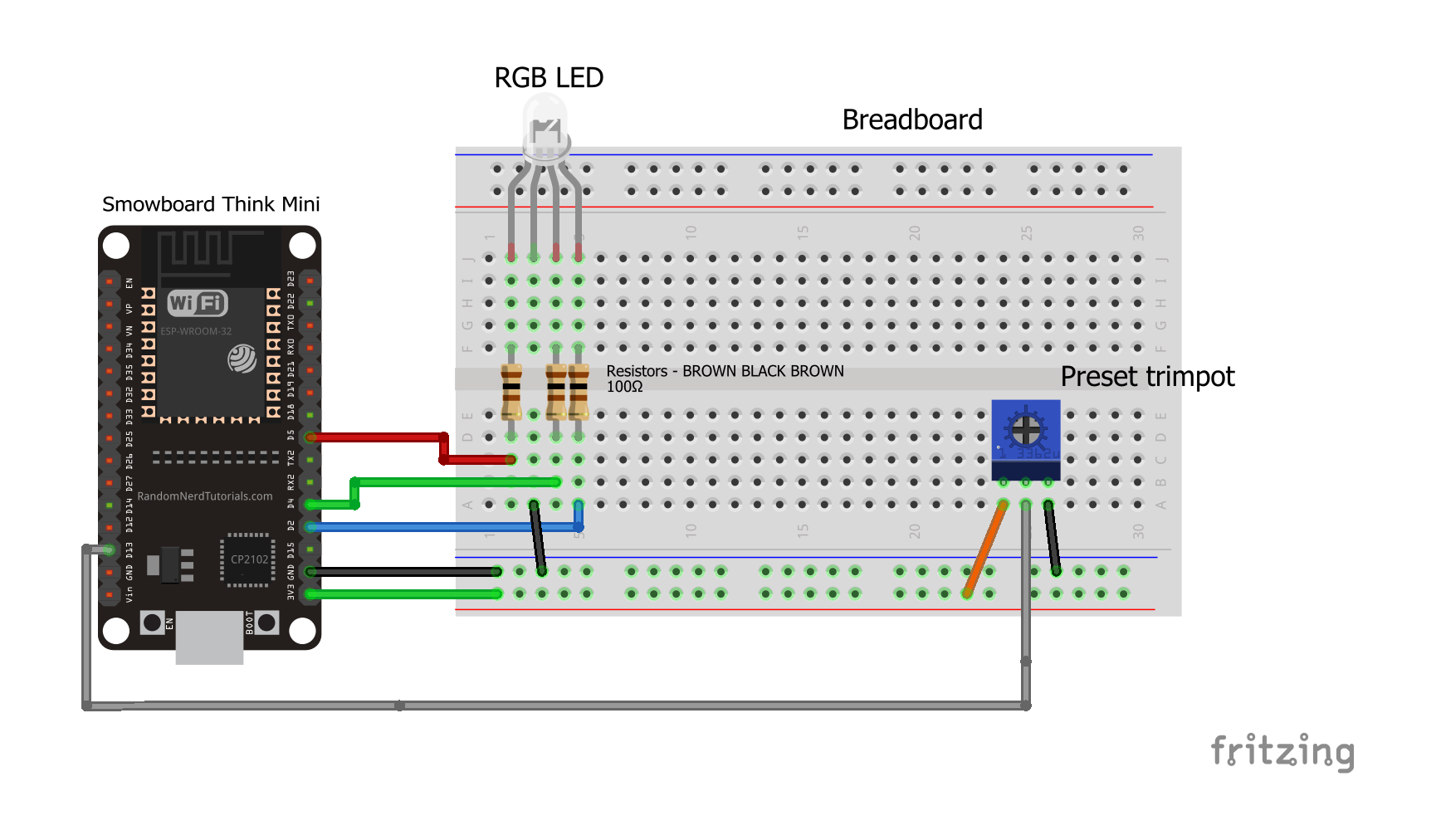
In this circuit, we use a RGB LED. The second pin of the LED (i.e the longest pin) is grounded by connecting it to the ground of Smowboard. The first pin of the LED is connected to pin number 5 of the Smowboard. The third pin is connected to pin number 4 of the Smowboard while the fourth pin is connected to pin number 2 of the Smowboard. The potentiometer's middle pin is connected to the pin number 13 of the Smowboard. From the remaining two pins of the potentiometer, one is connected to the ground of Smowboard while other is connected to the 3V3 pin of Smowboard.
The Smowboard reads the analog values from the potentiometer. The analog values read from the potentiometer are mapped to a certain range using Smowcode. Depending on the mapped values, the three pins of RGB LED will give different colours.
Flow
[{"id":"e0283091.3c1ef","type":"tab","label":"Flow 1","disabled":false,"info":""},{"id":"305f7574.ceb11a","type":"common/on interval","z":"e0283091.3c1ef","config_props":{"name":"","interval":"0.05"},"outputProps":{},"dependency_set":{},"x":190,"y":180,"wires":[["2b4622e6.04f4de"]]},{"id":"2b4622e6.04f4de","type":"smow_adc/analog read","z":"e0283091.3c1ef","config_props":{"name":"","config":"898d1bbd.e0a268"},"outputProps":{},"outputs":[{"variables":[{"name":"digital value","value":"digital_value"}]}],"dependency_set":{},"x":390,"y":180,"wires":[["678df32f.7143bc"]]},{"id":"678df32f.7143bc","type":"smow_util/map","z":"e0283091.3c1ef","config_props":{"name":"","input":"digital_value","x1":"0","x2":"4095","y1":"0","y2":"360"},"outputProps":{},"outputs":[{"variables":[{"name":"mapped","value":"mapped"}]}],"dependency_set":{},"x":610,"y":180,"wires":[["dbff97bd.f7eb18"]]},{"id":"dbff97bd.f7eb18","type":"smow_util/hsv rgb","z":"e0283091.3c1ef","config_props":{"name":"","conversion_type":"0","hue":"mapped","sat":"100","val":"100","red":"0","green":"100","blue":"100"},"outputProps":{},"outputs":[{"variables":[{"name":"Hue(°) or Red(%)","value":"hue_or_red"},{"name":"Sat(%) or Green(%)","value":"sat_or_green"},{"name":"Val(%) or Blue(%)","value":"val_or_blue"}]}],"dependency_set":{"hsv2rgb":true,"rgb2hsv":false},"x":860,"y":180,"wires":[["64396aa6.e6eaf4"]]},{"id":"64396aa6.e6eaf4","type":"smow_pulse/analog write","z":"e0283091.3c1ef","config_props":{"name":"","config":"c2906e06.f1bf7","duty_cycle":"hue_or_red","frequency":"1000","h_point":"0"},"outputProps":{},"dependency_set":{},"x":300,"y":300,"wires":[["b774eadc.657818"]]},{"id":"b774eadc.657818","type":"smow_pulse/analog write","z":"e0283091.3c1ef","config_props":{"name":"","config":"ae37d5f4.c3b1d8","duty_cycle":"sat_or_green","frequency":"1000","h_point":"0"},"outputProps":{},"dependency_set":{},"x":530,"y":300,"wires":[["1c0efe2d.570852"]]},{"id":"1c0efe2d.570852","type":"smow_pulse/analog write","z":"e0283091.3c1ef","config_props":{"name":"","config":"5079f225.3a3bac","duty_cycle":"val_or_blue","frequency":"1000","h_point":"0"},"outputProps":{},"dependency_set":{},"x":760,"y":300,"wires":[[]]},{"id":"898d1bbd.e0a268","type":"smow_adc/adc config","z":"","config_props":{"name":"","input_type":"0","pin":"21","non_gpio_input":"0","atten":"3","adc_bit_width":"3","samples":"2","v_ref":"1100","unit":"1","channel":"0"},"outputProps":{},"dependency_set":{"false_dep":false,"input_type_pin":true,"input_type_non_gpio_pad":false,"adc_unit1":false,"adc_unit2":true,"adc_ch0":false,"adc_ch1":false,"adc_ch2":false,"adc_ch3":false,"adc_ch4":false,"adc_ch5":false,"adc_ch6":false,"adc_ch7":false,"adc_ch8":false,"adc_ch9":false}},{"id":"c2906e06.f1bf7","type":"smow_pulse/analog write config","z":"","config_props":{"name":"","pin":"5","duty_resolution":"11","timer_num":"0","led_channel":"0","clk_config":"0","speed_mode":"0"},"outputProps":{},"dependency_set":{}},{"id":"ae37d5f4.c3b1d8","type":"smow_pulse/analog write config","z":"","config_props":{"name":"","pin":"4","duty_resolution":"11","timer_num":"0","led_channel":"1","clk_config":"0","speed_mode":"0"},"outputProps":{},"dependency_set":{}},{"id":"5079f225.3a3bac","type":"smow_pulse/analog write config","z":"","config_props":{"name":"","pin":"2","duty_resolution":"11","timer_num":"0","led_channel":"2","clk_config":"0","speed_mode":"0"},"outputProps":{},"dependency_set":{}}]
To import this code to the Studio, copy it and paste it into the import nodes dialog box in the import section.
Lets understand the code,
- The flow starts with an
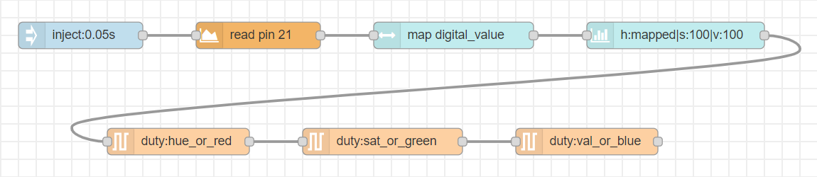
on intervalnode. All next nodes connected to it get triggered repeatedly after the specified interval of time. - Double click on the node to change its properties.
- We set the time interval of the
on-intervalnode to 0.05 seconds. - We connect an
analog readnode to read analog values from the potentiometer. Configure the node by clicking on the pencil icon on the 'input' property of the node. We set the 'Input type' as pin and 'pin' to 21 as the potentiometer is connected to the pin number 21 of Smowboard. - Click on
AddandDoneto complete the configuration. - The output of this node is 'digital_value' variable which is passed on to the next node.
- Now, we use a
mapnode to map the analog values read from the potentiometer. Set the 'input' property of the node as 'digital_value' variable which is obtained from the previous node. We set the values of x1, x2, y1, y2 as 0, 4095, 0 and 360 respectively. - The values read from the
analog readnode will be mapped to scale from 0 to 360. The output of this node is 'mapped' variable which will be passed to the next node. - We use a
hsv rgbnode to convert 'hsv' values to 'rgb' values for colour representation. We set the 'convert' property as 'HSV to RGB'. We set the 'Hue (°)' property as 'mapped' variable which is obtained from the previous nodemap. The 'Saturation (%)' and 'Value (%)' properties are set to 100. - The 'hsv rgb` node has three output variables namely 'hue_or_red', 'sat_or_green' and 'val_or_blue'.
- We now connect three
analog writenodes. Configure the nodes by clicking on the pencil icon on the 'output' property of the nodes. - For the first node set the 'Output pin' as 5. Set the 'Timer' to 'timer 0' and 'Ledc channel' to 'channel 0'.
- Click on
AddandDoneto complete the configuration. - Set the 'Intensity' to 'hue_or_red' variable.
- For the second node set the 'Output pin' as 4. Set the 'Timer' to 'timer 0' and 'Ledc channel' to 'channel 1'.
- Click on
AddandDoneto complete the configuration. - Set the 'Intensity' to 'sat_or_green' variable.
- For the third node set the 'Output pin' as 2. Set the 'Timer' to 'timer 0' and 'Ledc channel' to 'channel 2'.
- Click on
AddandDoneto complete the configuration. - Set the 'Intensity' to 'val_to_blue' variable.
- Now, we upload the code to the Smowboard using the
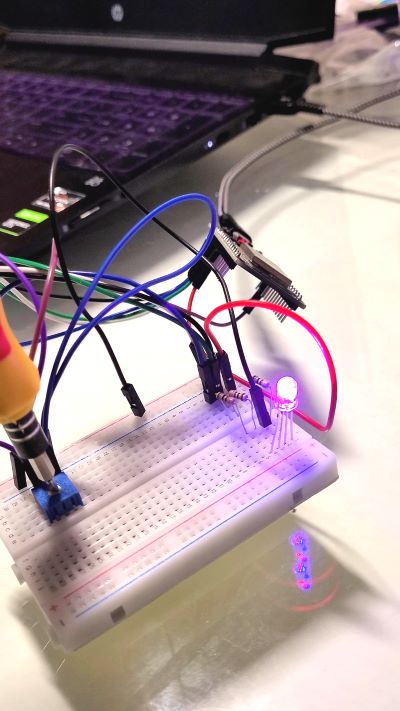
uploadbutton on the Studio. - We can see that when we rotate the shaft of the potentiometer using screw driver, the
analog readnode reads different analog values due to which we obtain various colours on the RGB LED.
Output
Learn Coding and Electronics easily using Smowcode.