Manually controlled DC Motor
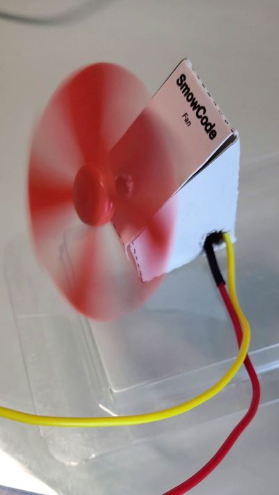
In this project, we build a manually conrolled fan. We turn ON or turn OFF the fan by clicking the push buttons and control the speed of the fan using the potentiometer.
Circuit
Components
- 1 Smowboard Think Mini
- 1 L293D IC
- 1 DC Motor
- 1 Fan propeller
- 1 potentiometer
- 1 Screw driver
- 2 push buttons
- 8 male-to-male jumper wires
- 8 male-to-female jumper wires
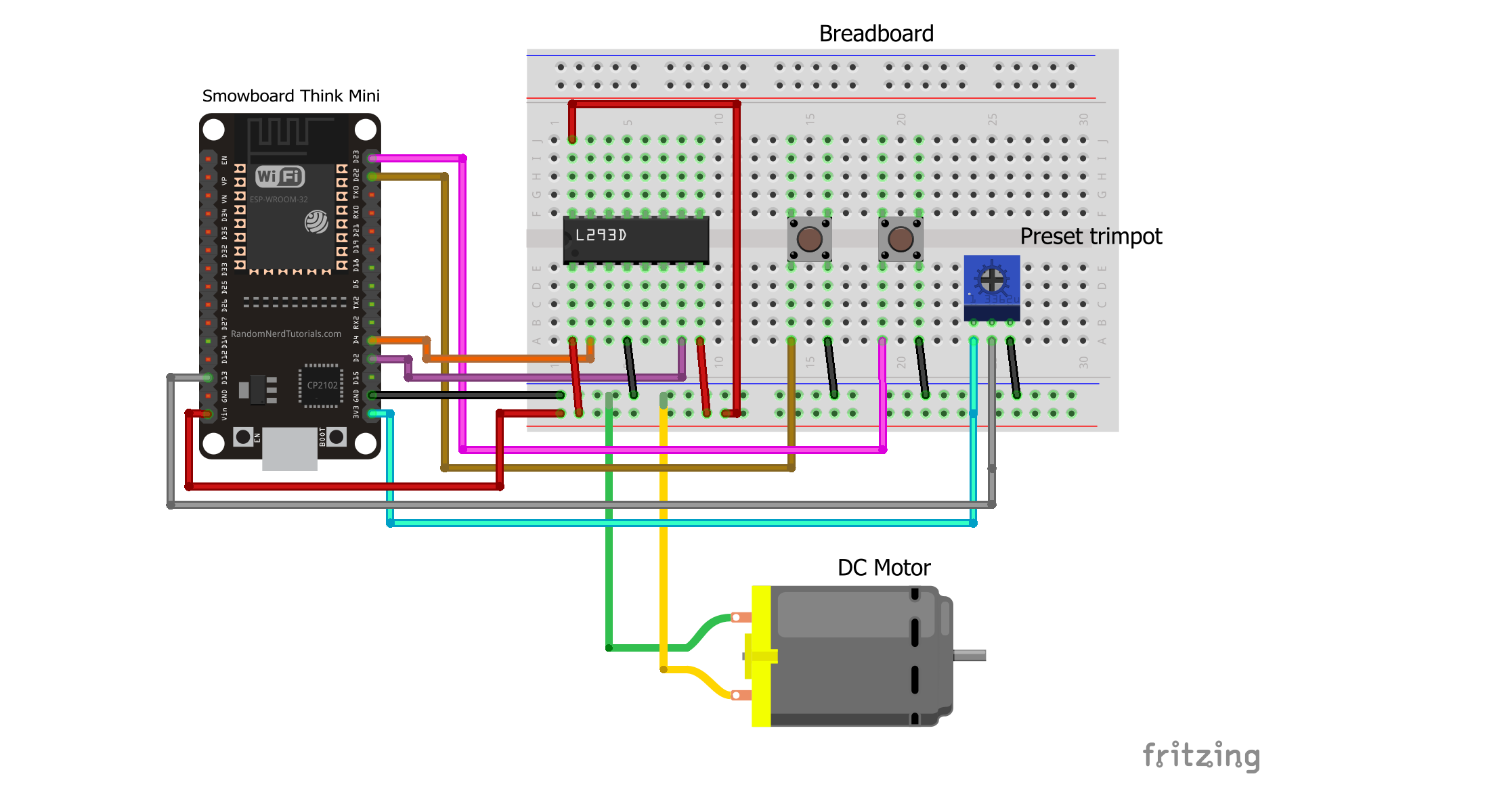
In this circuit, we use the L293D IC to control the DC Motor. We connect the pin number 1 of the IC which is the ENABLE pin to the Vin pin of Smowboard. We also connect the pin number 8 of the IC which is Vcc2 pin and the pin number 16 of the IC which is Vcc1 pin to the Vin pin of Smowboard. The IC is grounded by connecting its pin number 4 which is the ground pin to the ground of Smowboard. The pin number 2 of the IC which is the INPUT1 pin is connected to the pin number 4 of Smowboard. The INPUT2 pin of the IC which is pin number 7 is connected to the pin number 2 of Smowboard. These two input pins are controlled by the Smowboard. We connect the pin number 3 of IC which is the OUTPUT1 pin and pin number 6 of the IC which is the OUTPUT2 pin to the DC Motor. We connect a fan propeller to the shaft of DC Motor which works as a fan. We use two push buttons to turn ON or OFF the fan. We ground the push buttons by connecting one of their pins to ground of Smowboard. The other pin of first button is connected to pin number 22 of Smowboard while that of the second button is connected to pin number 23 of Smowboard. The push buttons will be controlled using the Smowboard. We use a potentiometer to control the speed of the fan. The potentiometer is grounded by connecting its ground pin to the ground of Smowboard. The power supply is provided to the potentiometer by connecting its Vcc pin to the 3V3 pin of Smowboard. The middle pin of the potentiometer is connected to the pin number 13 of the Smowboard.
The Smowboard controls the state of the motor with the help of the motor driver IC. The state of the motor is manually controlled using push buttons. When one push button is clicked, the Smowboard sends a signal to the IC to turn OFF the motor. When the other push button is clicked, the Smowboard sends a signal to turn ON the motor. Thus, the motor is turned ON or OFF using push buttons. The speed of the fan is controlled using a potentiometer. When the potentiometer rotates, the Smowboard smartly reads different analog values from the potentiometer and sends different signals to the motor driver IC depending on the value read from the potentiometer. Thus, the motor rotates at different speeds.
Project 1: Fan controlled using push buttons
Flow
[{"id":"7abf82d9.c8950c","type":"tab","label":"Flow 1","disabled":false,"info":""},{"id":"d322702e.e7676","type":"smow_pin/on button click","z":"7abf82d9.c8950c","config_props":{"name":"","pin_number":"22","connection_type":"0","auto_pull_up_down":"true"},"outputProps":{},"dependency_set":{},"x":250,"y":120,"wires":[["5744833d.e85d9c"]]},{"id":"5744833d.e85d9c","type":"smow_motor/dc motor","z":"7abf82d9.c8950c","config_props":{"name":"","motor":"43f045d7.4d2a6c","on_off":"1","dir":"0"},"outputProps":{},"dependency_set":{"dir_visibility":true},"x":470,"y":120,"wires":[[]]},{"id":"91181e85.83a48","type":"smow_pin/on button click","z":"7abf82d9.c8950c","config_props":{"name":"","pin_number":"23","connection_type":"0","auto_pull_up_down":"true"},"outputProps":{},"dependency_set":{},"x":250,"y":220,"wires":[["a3af674b.2718e8"]]},{"id":"a3af674b.2718e8","type":"smow_motor/dc motor","z":"7abf82d9.c8950c","config_props":{"name":"","motor":"43f045d7.4d2a6c","on_off":"0","dir":"0"},"outputProps":{},"dependency_set":{"dir_visibility":false},"x":470,"y":220,"wires":[[]]},{"id":"43f045d7.4d2a6c","type":"smow_motor/dc motor config","z":"","config_props":{"name":"","motor_mode":"0","pin1":"2","pin2":"5"},"outputProps":{},"dependency_set":{"mode_2_pin":false}}]
To import this code to the Studio, copy it and paste it into the import nodes dialog box in the import section.
Lets understand the code,
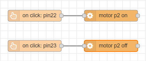
- The flow starts with an
on button clicknode. This node gets triggered when a button is clicked. - Double click on the node to change its properties.
- We set the 'pin no.' property as 22 as we have connected one push button to the pin number 22 of Smowboard.
- We connect a
dc motor node. Configure the node by clicking on the pencil icon on the 'Motor' property of the node. Set the 'Motor Mode' to 1 pin (no direction). Set the 'pin 1' value as 2. - We now click on
AddandDoneto complete the configuration - We set the 'switch' property to 'Turn ON'. This will keep the fan ON.
- Now, we add another
on button clicknode. We set its 'pin no.' property as 23 as we have connected the second push button to the pin number 23 of Smowboard. - We use the
dc motornode again and sets its 'switch' property to 'Turn OFF'. This will turn OFF the fan. - Now, we upload the code to the Smowboard using the
uploadbutton on the Studio. - We can see that when we click the first push button the fan is turned ON and when we click the second push button the fan is turned OFF.
Output
Project 2: Speed controlled fan using potentiometer
Flow
[{"id":"39733b7c.03c494","type":"tab","label":"Flow 5","disabled":false,"info":""},{"id":"c78118d2.896e18","type":"common/on start","z":"39733b7c.03c494","config_props":{"name":""},"outputProps":{},"dependency_set":{},"x":360,"y":120,"wires":[["e98d79d8.8baa08"]]},{"id":"e98d79d8.8baa08","type":"smow_pin/write","z":"39733b7c.03c494","config_props":{"name":"","pin_number":"4","level":"0"},"outputProps":{},"dependency_set":{},"x":560,"y":120,"wires":[[]]},{"id":"887992e7.b1a93","type":"common/on interval","z":"39733b7c.03c494","config_props":{"name":"","interval":"0.1"},"outputProps":{},"dependency_set":{},"x":220,"y":240,"wires":[["5615e7aa.e34648"]]},{"id":"5615e7aa.e34648","type":"smow_adc/analog read","z":"39733b7c.03c494","config_props":{"name":"","config":"13f02e81.3405b1"},"outputProps":{},"outputs":[{"variables":[{"name":"digital value","value":"digital_value"}]}],"dependency_set":{},"x":430,"y":240,"wires":[["5e42b606.f188f8"]]},{"id":"5e42b606.f188f8","type":"smow_util/map","z":"39733b7c.03c494","config_props":{"name":"","input":"digital_value","x1":"0","x2":"4095","y1":"0","y2":"100"},"outputProps":{},"outputs":[{"variables":[{"name":"mapped","value":"mapped"}]}],"dependency_set":{},"x":670,"y":240,"wires":[["499b6c84.4ed6b4"]]},{"id":"499b6c84.4ed6b4","type":"smow_pulse/analog write","z":"39733b7c.03c494","config_props":{"name":"","config":"c1529618.26ab98","duty_cycle":"mapped","frequency":"1000","h_point":"0"},"outputProps":{},"dependency_set":{},"x":910,"y":240,"wires":[[]]},{"id":"13f02e81.3405b1","type":"smow_adc/adc config","z":"","config_props":{"name":"","input_type":"0","pin":"13","non_gpio_input":"0","atten":"3","adc_bit_width":"3","samples":"2","v_ref":"1100","unit":"1","channel":"4"},"outputProps":{},"dependency_set":{"false_dep":false,"input_type_pin":true,"input_type_non_gpio_pad":false,"adc_unit1":false,"adc_unit2":true,"adc_ch0":false,"adc_ch1":false,"adc_ch2":false,"adc_ch3":false,"adc_ch4":true,"adc_ch5":false,"adc_ch6":false,"adc_ch7":false,"adc_ch8":false,"adc_ch9":false}},{"id":"c1529618.26ab98","type":"smow_pulse/analog write config","z":"","config_props":{"name":"","pin":"2","duty_resolution":"11","timer_num":"0","led_channel":"0","clk_config":"0","speed_mode":"0"},"outputProps":{},"dependency_set":{}}]
To import this code to the Studio, copy it and paste it into the import nodes dialog box in the import section.
Lets understand the code,
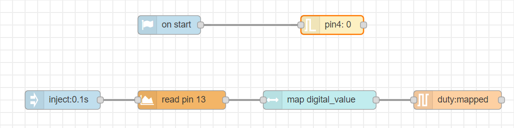
- The flow starts with an
on intervalnode. All next nodes connected to it get triggered repeatedly after the specified interval of time. - Double click on the node to change its properties.
- We set the time interval of the
on-intervalnode to 0.1 seconds. - We connect an
analog readnode to read the analog values from potentiometer. This will define the intensity of speed for the potentiometer. Configure the node by clicking on the pencil icon on the input property of the node. Set the 'Pin' value as 13. Set the 'voltage range' as 150 - 2450mV (attenuation 11dB). - We then click on
Addanddoneto complete the configuration. - The output of this node is 'digital_value' which will be passed on to the next node.
- Now, we connect a
mapnode to map the 'digital_values' variable which is the output of theanalog readnode. For this, we set the 'input' property of the node as 'digital_values'. Set the properties x1 , x2 , y1 and y2 as 0, 4095, 0 and 100 respectively. - The output of this node is 'mapped' which will be passed on to the next node.
- This will map the analog values obtained from potentiometer to a scale from 0 to 100.
- Next, we use an
analog writenode to write the mapped values to the motor. Configure the node by clicking on the pencil icon on the output property of the node. Set the 'output pin' as 2 as we have have connected the pin number 2 of Smowboard to the motor. - We then click on
Addanddoneto complete the configuration. - Set the 'intensity' property of the node as 'mapped' which is the output of the previous node i.e
map. - Now, to turn OFF the second pin of the Motor which is connected to pin number 4 of Smowboard, we have to set the pin number 4's level as 0
- For this, we use an
on startnode and connect apin writenode to it. We set the 'pin number' property as 4 and 'pin level' property as 0. This will turn OFF the second pin of the motor. - Now, we upload the code to the Smowboard using the
uploadbutton on the Studio. - We now rotate the shaft of the potentiometer using a screw driver.
- We can see that the fan does not rotate initially and as we rotate the potentiometer shaft, the speed of the fan keeps increasing. The fan rotates at maximum speed when the shaft is rotated to its full capacity. Again, when we roatate the shaft in reverse direction the speed goes on decreasing.
Output
Learn Coding and Electronics easily using Smowcode.